Energy · Water · Resources

Technologies for an independent, clean future

N2 TRANS develops and delivers solutions for energy storage, drinking water from air, power from biomass and wind energy – efficient, low-emission and scalable.

Voltumna® Synergy Storage Power Plant

The Voltumna® Synergy Storage Power Plant is a combination of the Voltumna® Nitrogen Storage and the Voltumna® Battery Container. The Voltumna Synergy Storage Power Plant differs from its competitors by precisely this combination of liquid air and a high-performance battery. As a result, the synergy storage system achieves a charge and discharge rate of 5 C. Practically all large-scale storage systems worldwide operate at 0.2 - 0.5 C, occasionally at 1 C.

Voltumna Hybridspeicher

The Voltumna® Synergy Storage Power Plant is adaptable and can be used at all levels of the electricity system: to support power generation, to stabilise transmission and distribution grids and as a backup power source for end users, as well as a fast charging station for the expansion of e-mobility. Our patented cryogenic technology is based on best practices from the fields of turbo machinery, engine and generator technology, power generation and industrial gases.

Advantages of the Voltumna® Synergy Storage Power Plant

  • Our power storage unit combines nitrogen technology with a high-performance battery
  • Active battery management in combination with nitrogen as storage medium
  • Overall efficiency of ~ 54% without external heat source
  • Additional heat energies increase the efficiency exponentially
  • up to 6C charging
  • up to 6C discharge
  • Wider operating temperature range
  • Charging efficiency of more than 98%
  • better performance at low temperatures
  • Long life up to > 50,000 charge cycles at 0.5C
  • Minimal overheating or heat emission during operation (waste heat during the charging process as well as during conversion can be used again for nitrogen power production)
  • Containers are stackable and can therefore be scaled as required
  • 4C battery containers from 1.112MWh capacity and up to 5 MW output
  • With N2 (nitrogen) there is no environmental pollution at all
  • So-called "efficiency losses" are absolutely negligible, as we do not cause any damage to nature or people with our technology.
  • We are able to cushion energy bottlenecks with the cleanest technology on earth "N2"
  • With the help of our overall technology, we can cleanly (without "any pollution") and directly intervene in current energy supply to counteract enormous gaps in supply and similar situations to ensure neutral grid stability.
  • All this without causing even the slightest damage to nature.
  • 4C battery containers from 1.112MWh capacity and up to 5 MW output
  • Hybrid storage battery + nitrogen from 20MWh cpacity and starting from 5 MW output

Voltumna® Nitrogen Storage

The Voltumna® Nitrogen Storage System is a cryogenic energy storage system. Cryogenic energy storage refers to the use of cryogenic liquids, such as liquid air or liquid nitrogen, as energy storage. With liquid air storage, an incredibly high energy density can be achieved, and is thus comparable to batteries. This is 20 times higher than with air compression storage and a whole 400 times higher than with common pumped storage hydro power station. Energy storage is possible for up to 4 weeks with almost no losses. Our patented storage system is an ideal solution for transferring surplus electricity from summer to winter. Efficiencies of up to 93% can be achieved here (confirmed by expert opinion from the Swiss Federal Office of Energy).

Working principle of the Voltumna® Nitrogen Storage System

Stage 1: Charging the system

Using the standardised air separation process, air is separated into nitrogen (~78%), oxygen (~21%), argon (~0.93%) and other gases The nitrogen is cooled down to minus 196° Celsius in a liquefaction plant by using electrical energy until nitrogen liquefies. Approximately 700-800 litres of gaseous nitrogen become about 1 litre of liquid nitrogen.

Nitrogen
Stage 2: Energy Storage

The liquid nitrogen is stored in a cryogenic tank at low pressure, which acts as an energy store. Depending on the size, up to several GWh of energy can be stored.

Crogenic Tank
Stage 3: Energy Recovery

When electricity is needed, the liquid nitrogen is converted back into gas form via a patented pre-evaporator and further heat is added to the system via heat exchangers. This causes 1 litre of liquid nitrogen to expand again to 700-800 times its original size. If additional heat energy is added, e.g. from the stored heat from the compressors, this increases the efficiency exponentially. This creates a high-pressure gas from which energy is extracted in several patented stages and drives different motors, which in turn set several electric generators in motion to produce electricity.

Generator

Voltumna® High Capacity Battery Container

The Voltumna® high-performance battery container has an overall efficiency of more than 90 %, operates in a wide operating temperature range and has a long service life of > 50,000 charging cycles compared to other batteries. For grid-wide storage of electricity with long discharge times, N2 TRANS' system reduces many of the constraints imposed by other storage technologies. The Voltumna® Hybrid Storage System and likewise the Battery Storage Container alone have a small footprint without the liquefaction plant and can easily meet strict urban building codes.

Voltumna Battery Container

Another great advantage of this battery is its high recycling rate of over 90 %. It is non-toxic, non-flammable, there is no risk of explosion and the battery can be drilled, cut or hammered without danger.

Battery Cell Safety Tests

N2 TRANS Next-Generation Tyre Recycling

Fluidized pyrolysis, SynDiesel & Hygimed deashing – turning scrap tyres into premium resources

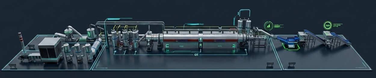
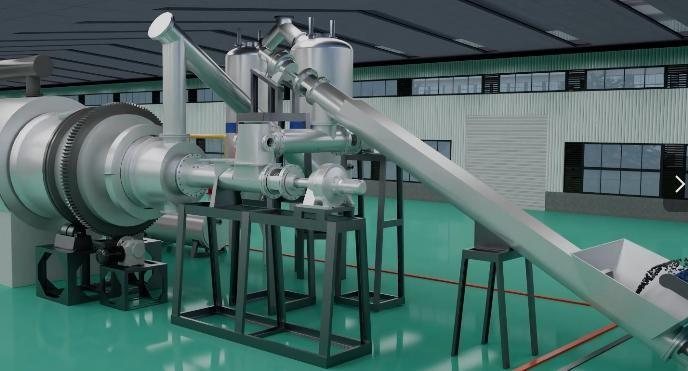
3D model of a complete plant for tyre pyrolysis, oil upgrading and rCB production

Our 360° circular-economy solution recovers scrap tyres completely: a continuous fluidized-bed pyrolysis breaks the rubber down into pyrolysis oil, syngas and pyrolytic carbon black. The oil is upgraded on site into market-ready synthetic diesel (SynDiesel), while the carbon black is purified without heat in the patented Hygimed process into high-grade recovered carbon black (rCB) – suitable for manufacturing new tyres. The syngas serves as the plant's heat source. A closed loop that maximises yield and minimises emissions.

Innovation 1: Continuous Fluidized-Bed Pyrolysis

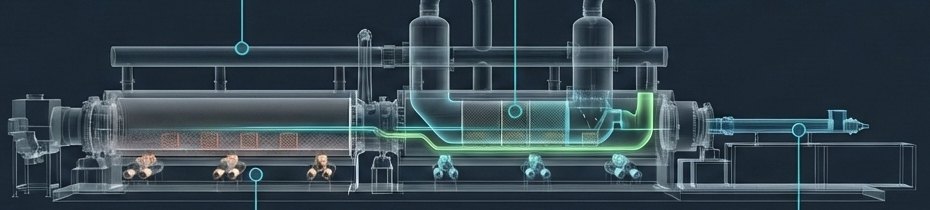
Unlike conventional fast pyrolysis, the fluidized-bed reactor uses a controlled, slow heating profile. This maximises the liquid fuel yield and preserves the structure of the carbon black. Thousands of spiral and dispersion plates inside the reactor ensure even heating and complete pyrolysis – without coking.

Cut-away view of the fluidized-bed pyrolysis reactor
3 Months Non-Stop

Fully automatic, unattended continuous operation minimises downtime and labour costs.

Zoned & Slow Heating

Independently controlled heating zones – optimal conditions from devolatilisation to carbonisation.

Integrated Catalysis

Advanced reactor geometry with catalyst mixing zones for efficient cracking.

High-Temperature Steel

Reactor made of 14 mm SS 310S, creep- and oxidation-resistant, insulated with aluminium silicate wool.

Dynamic Sealing

Oxygen-free feeding during operation – no air ingress, no odour, no risk of explosion.

Cool Carbon Black Discharge

Discharge at ≤ 60 °C via a water-cooled section – no risk of auto-ignition.

Self-Cleaning Condensers

Automatic anti-blocking system ensures lasting heat-exchange efficiency.

Multi-Stage Emission Control

Cooler, dust collector, DeNOx and desulphurisation neutralise SOx, dioxins and particulates.

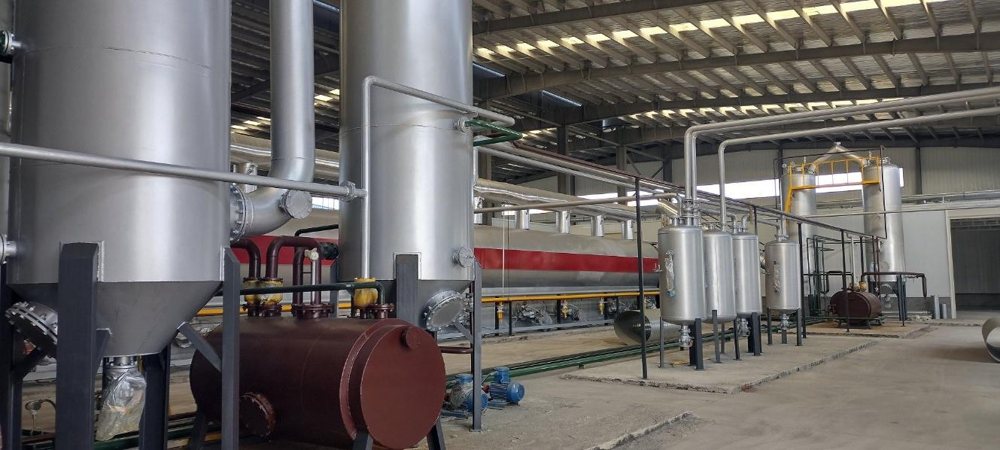
Pyrolysis line with condensation
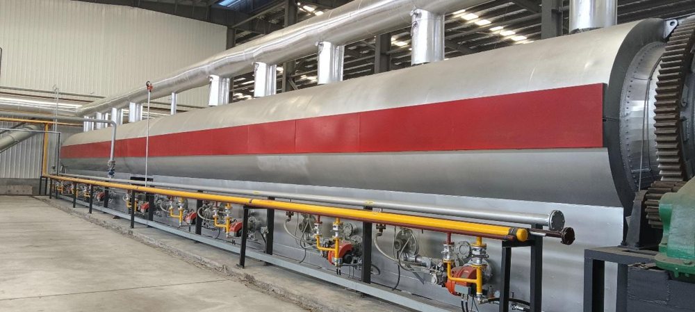
Pyrolysis reactor with zoned burners
Feeder with dynamic sealing
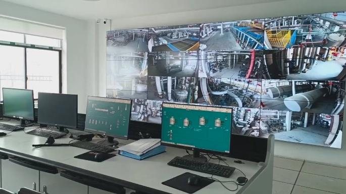
Control room & video monitoring

Key Data of the Pyrolysis Line

Capacity 30 t of tyre rubber per day per line – modular (e.g. 60–70 t/day with two lines)
Operation continuous, up to 3 months without stopping
Reactor Ø 1.6 m × 24 m, 14 mm wall thickness
Heating 6 burners fired with the non-condensable pyrolysis gas
Carbon black discharge three-stage, water-cooled, ≤ 60 °C
Control control cabinet with touch display, frequency-controlled drives
Flue gas treatment cooler, dust collector, DeNOx, desulphurisation & odour removal
Footprint approx. 60 × 10 m (pyrolysis line)

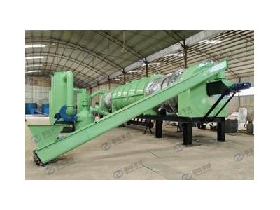
The pyrolysis line is supplied as a complete system: lifting conveyor and sealed feeder, rotary reactor with double-insulated bearing and sealing zones, three-stage carbon black discharge, oil-gas separator, condensers with automatic flushing, oil tanks, flame arrestors and flue gas treatment.

SynDiesel Upgrading to Synthetic Diesel

From pyrolysis oil to market-ready fuel – on site, without external processing

Standard tyre pyrolysis oil is viscous, high in sulphur and only moderately stable in storage. The integrated upgrading line cleans the syngas, enriches it with hydrogen and continuously distils the oil into synthetic diesel – with much lower sulphur content, lower viscosity and a higher flash point.

Syngas Cleaning & Buffering
Step 1
Syngas Cleaning & Buffering

A wash removes particles and CO2; buffer tank and cooling tower stabilise the gas flow, a compressor raises it to 20–50 bar.

Amine Scrubber & ZnO Filter
Step 2
Amine Scrubber & ZnO Filter

Deep purification of the syngas and final desulphurisation.

WGS Reactor (Water-Gas Shift)
Step 3
WGS Reactor (Water-Gas Shift)

Steam enriches the syngas to approx. 50 % hydrogen; an adiabatic cooler removes the moisture.

Continuous Distillation
Step 4
Continuous Distillation

The pyrolysis oil is continuously distilled into market-ready SynDiesel and stored in tanks.

Distillation Unit

Throughput 10 t of oil per day
Yield 85–90 % diesel; sulphur and asphalt levels adjustable on request
Feedstock pyrolysis oil, used mineral oil, crude oil
Power demand 18 kW
Heating pyrolysis oil, syngas, coal or natural gas
Operation continuous, unpressurised (< 0.02 MPa)
Staff 1–2 per shift, 24-h operation
Footprint approx. 25 × 35 m

Profitable at Every Stage

  • Low OPEX: 1–2 operators per shift and low energy demand, as syngas is recycled as the heat source
  • Low CAPEX: highly modular system that grows with demand
  • Two premium revenue streams: SynDiesel as fuel at market price and rCB N330/N550 for the tyre industry

Quality Advantage: SynDiesel vs. Standard Pyrolysis Oil

Parameter Standard pyrolysis oil Moderate treatment Complete treatment
Density (kg/L at 15 °C) 0.95–1.03 0.90–0.96 0.85–0.92
Viscosity (cSt at 40 °C) 6–15 4–10 2–6
Heating value (MJ/kg) 40–42 42–44 44–46
Sulphur content (%) 0.8–1.5 0.4–0.9 0.05–0.3
Aromatics (%) 55–75 45–65 25–50
Olefins (%) 10–25 5–15 < 5
Paraffins (%) 5–15 10–25 25–45
Flash point (°C) 20–35 30–45 40–60
Storage stability poor moderate good
Carbon residue (%) 3–8 2–5 1–3
Ash (ppm) 500–2,000 200–800 < 200

Comparative analysis of tyre pyrolysis oils, typical values.

Hygimed Deashing – Premium rCB from Scrap Tyres

Cold purification of pyrolytic carbon black – ash content below 0.7 %

The problem: conventional pCB

Raw pyrolytic carbon black (pCB) contains too many mineral impurities and steel residues. As such, it is unusable for high-quality tyre production.

The solution: Hygimed deashing

A patented (January 2026), heat-free process without aggressive chemicals reduces the ash content to below 0.7 % – the gateway to the premium market for recovered carbon black (rCB).

The 3-Stage Cold Purification Process


Stage 1
Mechanical Pre-Treatment

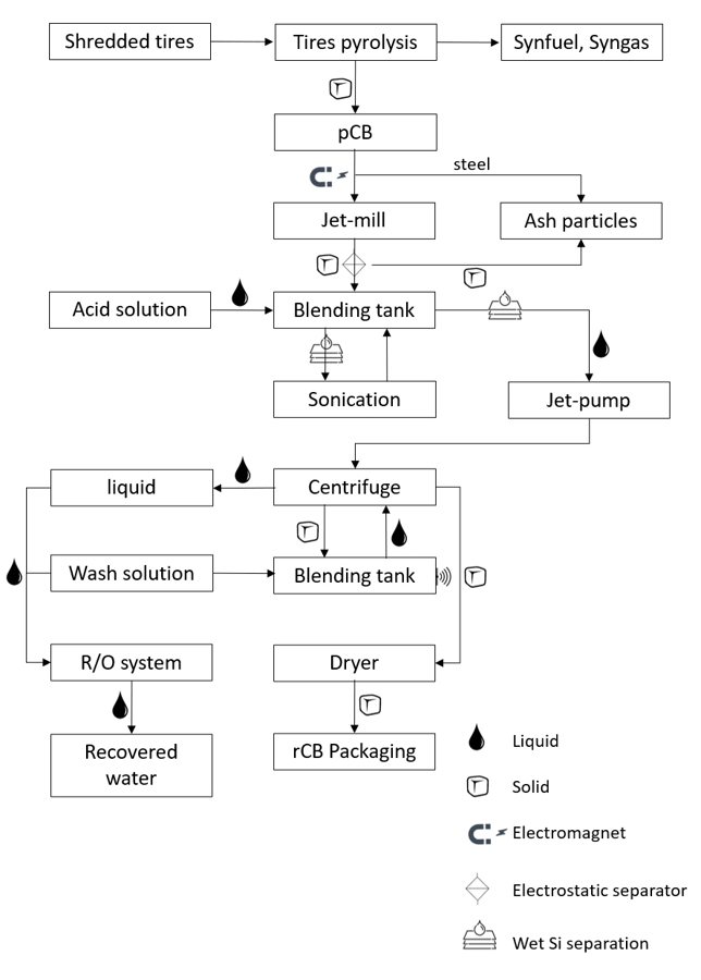
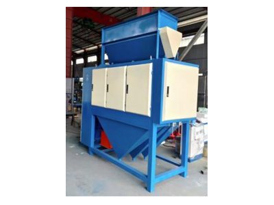
Magnetic separators remove steel residues, a jet mill grinds the pCB to ≤ 40 µm. Dry triboelectric separation removes a large share of the inorganic particles.


Stage 2
Chemical-Physical Purification

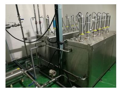
Controlled extraction with ultrasound and jet-pump hydrodynamics gently washes the ash out of surfaces and pores – without damaging the carbon matrix.


Stage 3
Oxygen-Free Drying

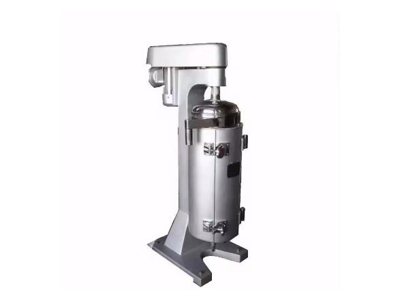
After washing and centrifuging, a rotary furnace dries the rCB in the absence of oxygen, heated with residual syngas. This improves BET surface area and dispersion in rubber compounds.

Process scheme of the deashing process: pyrolysis, jet mill, acid wash, sonication, centrifuge, dryer, reverse osmosis

The process runs continuously and requires no high-temperature treatment, aggressive chemicals or harmful residues. It takes the unique aggregate structure of carbon black particles into account and removes inorganic impurities from the surface and the pores without damaging the carbon matrix.

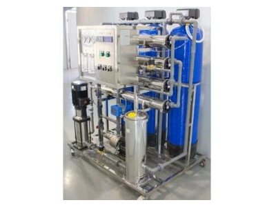
Wash water is recovered via a reverse osmosis unit. The technology suits compact on-site units as well as large industrial installations – a standard module processes 1,000 kg of pCB per hour.

Certified Premium Quality: ASTM N330 & N550

0.33 % Ash content limit ≤ 0.75 %
2.8 % Fines content limit ≤ 7 %
82 g/kg Iodine adsorption target 82 ± 5

Certified values. Our rCB is not a waste product but an engineered material specified to ASTM D8178 that can replace fossil virgin carbon black (vCB) in the manufacture of tyres and technical rubber goods.

Competitive Edge: Hygimed vs. Industrial Standard

Parameter Industrial standard Hygimed deashing
Electricity demand high low
Heat demand very high very low (drying only)
CO2 emissions very high very low
NOx/SOx emissions very high none
Capital investment very high low
Complexity high simple
Mobility no yes
Scalability complex & expensive modular design
Hazardous waste high none
Operating costs very high very low

Main Components of the rCB Line

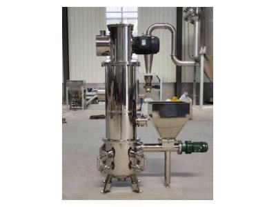
Jet mill
Jet mill
Triboelectric separator
Ultrasonic cleaning
Ultrasonic cleaning
Continuous centrifuge
Reverse osmosis
Reverse osmosis
Rotary dryer
Rotary dryer

Pictures for illustration only.

Ecological Dividend

Zero Waste

No aggressive chemicals, no harmful residues – scrap tyres are fully recovered and process water is reclaimed.

Minimal Emissions

Patented smoke scrubbers and syngas as heat source drastically cut NOx, SOx and CO2 emissions.

CO2 Credit

rCB replaces fossil-based virgin carbon black – with a positive carbon balance and potential for tradable CO2 certificates.

Real disruption happens when economic profit and ecological responsibility are united through technology.

N2 TRANS Water from Air

Atmospheric Water Generation (AWG) – Empowering Tomorrow, One Drop at a Time

Atmospheric Water Generation (AWG) transforms the boundless moisture in the air we breathe into a sustainable, inexhaustible asset. The result: absolute water independence.

  • Extracts pure drinking water directly from ambient humidity – optimal at 70 % relative humidity, functions down to 30 %.
  • Eliminates reliance on volatile municipal sources and environmentally damaging plastic supply chains.
  • Seamlessly scalable architecture – from compact residential units to heavy-duty industrial installations producing 3,000 litres per day.
Water drop
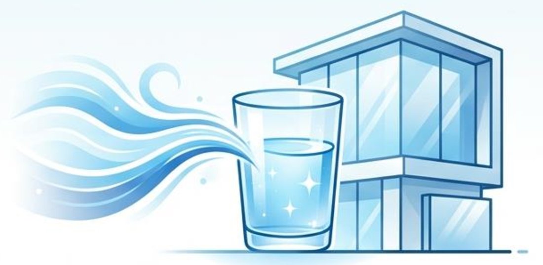
Drinking water generated directly from the air

The N2 TRANS Difference

100 % In-House Manufacturing

Ensures stringent quality control, robust material use (stainless steel & galvanized iron), and rapid, continuous technological innovation.

Zero Plastic & Zero Waste

Completely eliminates single-use plastics, toxic nanoplastics, and the carbon footprint associated with water logistics.

Patented Ozonization

Integrated, next-generation purification technology that destroys microorganisms without leaving harmful chemical residues.

Global SDG Alignment

Actively supports 8 UN Sustainable Development Goals, including Clean Water & Sanitation, Gender Equality, Sustainable Cities, and Climate Action.

The Science of Purity: 4-Step Filtration

4-step filtration process

Purification in four steps

Step 1: Air Filter

An anti-static filter removes dust and micro-particles from the ambient air before condensation.

Step 2: Water Dust Filter

Removes external physical particles as the condensation process begins in the collection tank.

Step 3: Multi-Stage Water Filter

A rigorous sequence of sediment, pre-carbon, ultrafiltration (UF), and post-carbon filters removes odours, organics (up to 5 microns), and dissolved salts, finishing with a mineral cartridge to restore essential nutrients.

Step 4: Ozone Generator

The final, active purification stage ensures crystal-clear, bacteria-free water in the purified storage tank.

Next-Generation Disinfection: The Ozone Advantage

3,000× more effective than chlorine
3,741× more effective than UV

Our patented ozone generator acts as a potent oxidizer and disinfectant. It reliably destroys microorganisms without leaving the harmful chemical residues associated with traditional municipal water treatment – ensuring the purest form of drinking water.

Dewpoint Series

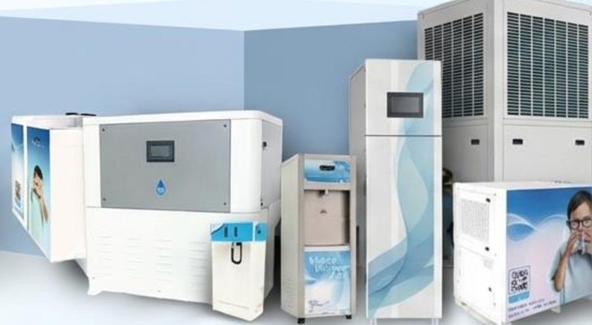
A solution for every scale – from 25 to 3,000 litres of drinking water per day

Dewpoint Series atmospheric water generators

Residential & Office 25 L / day

Compact, quiet, and designed for daily household or small team consumption. Operating at 230 V AC / 50 Hz with efficient 500 W power consumption.

Dewpoint Smart

Smart

25 L / day
Storage tank 17 L
Power consumption 500 W
Weight 62 kg

Highly portable; doubles as an indoor dehumidifier and air filter.

Dewpoint Smart+

Smart+

25 L / day
Storage tank 19 L total
Power consumption 500 W + 500 W
Weight 67 kg

Integrated hot water option for versatile beverage needs.

Dewpoint Prime

Prime

25 L / day
Storage tank 23 L
Power consumption 500 W
Weight 75 kg total

Split-unit design for ultimate space saving.

Commercial 100 – 500 L / day

Robust, environment-friendly 230 V AC / 50 Hz systems engineered for medium-to-large foot traffic in call centers, hospitals, schools, and corporate complexes.

Dewpoint Super

Super

100 L / day
Storage tank 62 L
Power consumption 2 kW
Refrigerant R-410A

Small factories and call centers (serving 50–75 people).

Dewpoint Hyper

Hyper

250 L / day
Storage tank 220 L
Power consumption 3 kW
Refrigerant R-410A

Large commercial offices, educational institutions, and hospitals.

Dewpoint Mega

Mega

500 L / day
Storage tank 220 L
Power consumption 7 kW
Refrigerant R-410A

Mid-sized commercial complexes requiring high-volume reliability.

Industrial & Community 1,000 – 3,000 L / day

High-yield 415 V AC / 50 Hz, 3-phase systems built for factories, extreme environments, outdoor installations, community supply, and large-scale disaster relief.

Dewpoint Ultra

Ultra

1,000 L / day
Storage tank 395 L
Power consumption 13 kW
Weight 700 kg

Large-scale applications, remote locations, and rapid disaster relief.

Dewpoint Royale

Royale

2,200 L / day
Storage tank 750 L
Power consumption 26 kW
Weight 1,400 kg

Outdoor, industrial compact design in galvanized iron & stainless steel.

Dewpoint Amber

Amber

3,000 L / day
Storage tank 2,500 L
Power consumption 40 kW
Weight 6,000 kg

Fully self-contained 20 ft container-based unit.

The Economics of Water Independence

Traditional Sourcing

  • Volatile municipal utility costs
  • Endless logistical overhead for bottled water delivery
  • Hidden disposal fees for plastic waste
  • High supply chain vulnerability

The AWG Paradigm

  • Highly predictable OPEX (fixed electricity + standard consumables)
  • Zero logistics and zero plastic disposal costs
  • Complete protection against local water scarcity
Strategic shift: Equipment rental and OPEX models turn capital expenditure into a predictable monthly operating expense that guarantees water security.

Confront Water Scarcity Head-On.

Partner with N2 TRANS GmbH to secure your sustainable, independent water future today.

Get in touch

N2life Power from Biomass

Transforming organic waste into clean energy – without incineration

The N2life system is a non-incineration thermal technology that converts organic waste – biomass, food waste, sludge, manure and even waste containing up to 30 % plastic – into hydrogen-rich syngas. An AI-controlled generator turns it into electricity right on site, transforming a costly disposal liability into reliable, off-grid baseload power.

  • Zero incineration: no smoke, no wastewater – only dry ash remains
  • 600–1,000 kWh of electricity per ton of dry biomass
  • Fully automatic and AI-controlled, requiring minimal manual intervention
  • Integrated CO2 absorption for exceptionally low emissions
  • Besides electricity, also hydrogen, synthetic natural gas (SNG) or heat
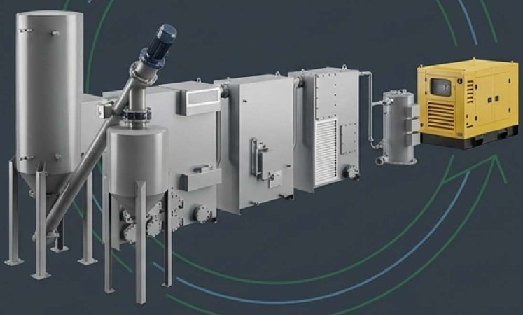
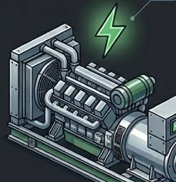
N2life biomass gasification system with generator
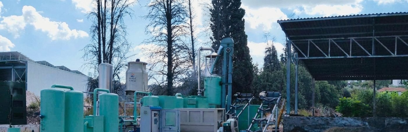
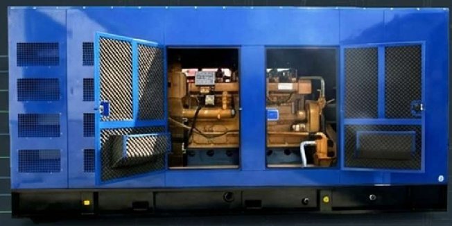
N2life system in operation

Infinite Flexibility: Your Waste is the Fuel

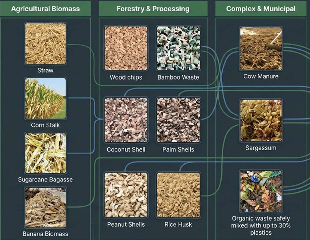
N2life processes a broad range of organic residues, turning unpredictable waste into a predictable, high-yield energy stream. Requirements: moisture below 20 % and a particle size of max. 5 cm – an optional pretreatment line prepares the material accordingly.

Suitable feedstock: straw, corn stalk, bagasse, wood chips, shells, rice husk, manure, sargassum
Agricultural Biomass

Straw, corn stalk, sugarcane bagasse, banana biomass

Forestry & Processing

Wood chips, bamboo waste, coconut, palm and peanut shells, rice husk

Municipal & Industrial

Cow manure, sargassum, food waste, sludge and organic waste mixed with up to 30 % plastics

The 4-Stage Process

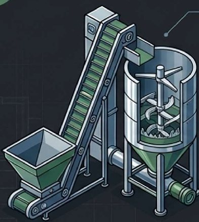
Pretreatment
Stage 1
Pretreatment

Automatic dewatering, shredding and mixing. Even organic waste mixed with plastics is homogenized into a uniform feedstock.

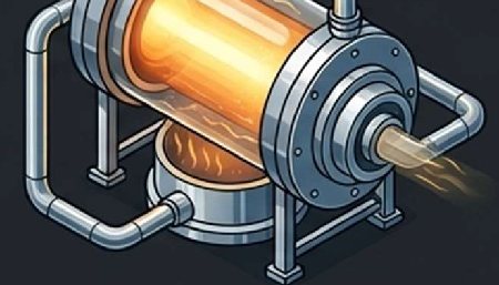
Thermal Decomposition
Stage 2
Thermal Decomposition

Operating at 320–700 °C, the reactor performs carbonization, oxidation and thermal oxidation-reduction, extracting raw syngas without combustion.

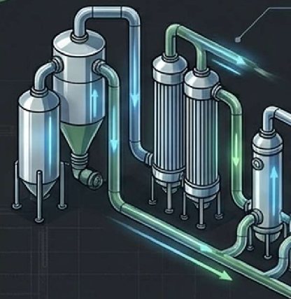
Syngas Purification
Stage 3
Syngas Purification

The gas is cooled, de-dusted, scrubbed and filtered. Integrated CO2 absorption guarantees exceptionally low emissions.

Electricity Generation
Stage 4
Electricity Generation

The hydrogen-rich syngas feeds an AI-controlled generator for continuous electricity – or is diverted to hydrogen enrichment and SNG production.

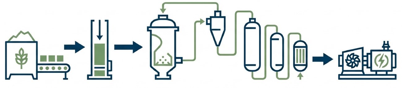
Process flow from biomass to electricity
  1. Biomass storage & conveyor
  2. Skip charger
  3. Gasification reactor
  4. Cyclone dust removal
  5. Gas cleaning & cooling
  6. Syngas generator

Technology in Detail

  • Reversed flow with a controlled vacuum system at the bottom of the reactor
  • Enlarged oxidation zone for more stable, uniform reactions
  • Complete containment of all process gases – without complex high-pressure systems
  • Two-stage purification for particle-free syngas before power generation
  • Vacuum principle: operation under negative pressure – in case of a leak, air flows in but no gas escapes
  • Encapsulated processes: fully closed reactor and gas handling systems
  • Explosion protection: continuous extraction prevents ignitable gas mixtures
  • CO monitoring: integrated sensors for permanent ambient air control
  • CE certified
  • Intelligent PLC system standardizes feedstock intake and optimizes gas composition in real time
  • Automatic start/stop, load sharing and alarm protection
  • Full remote monitoring and control
  • Automatic shutdown on abnormal pressure or temperature values
  • Clear LCD display, configurable in English and German
  • Continuous intake: waste is processed as it is generated
  • The reactor operates continuously for maximum thermal efficiency
  • Optional on-site gas storage buffers the syngas
  • On-demand generation: the genset delivers exactly when demand peaks, reducing peak tariff costs

N2life Models & Technical Data

Modular systems from 20 to 1,000 kW electrical output – for commercial and industrial sites
N2life syngas generator

Each system consists of the gasifier (HBF) and the matching syngas generator (HTG). The compact, modular design requires only 20–150 m² of space and can be installed directly at industrial or agricultural sites without special infrastructure.

Capacity 0.72–36 t of dry biomass per day
Electricity yield 600–1,000 kWh per ton of dry matter
Own consumption approx. 10 % of generator output

Syngas heating value approx. 4–4.5 MJ/Nm³
Waste heat optionally recoverable (approx. 5–10 % extra)
Footprint 20–150 m²
Gasifier Genset Biomass
(kg/h)
Biomass
(t/day)
Gross output

(kW)
Net output

(kW)
Electricity
(MWh/day)
Commercial Scale
HBF-60W HTG-20GF 30 0.72 20 17 0.48
HBF-100W HTG-30GF 45 1.08 30 27 0.72
HBF-120W HTG-40GF 60 1.44 40 36 0.96
HBF-150W HTG-50GF 75 1.8 50 45 1.2
HBF-200W HTG-60GF 90 2.16 60 55 1.44
HBF-250W HTG-80GF 120 2.88 80 72 1.92
HBF-300W HTG-100GF 150 3.6 100 90 2.4
Industrial & Utility Scale
HBF-500W HTG-150GF 225 5.4 150 135 3.6
HBF-600W HTG-200GF 300 7.2 200 180 4.8
HBF-900W HTG-300GF 450 10.8 300 270 7.2
HBF-1200W HTG-400GF 600 14.4 400 360 9.6
HBF-1500W HTG-500GF 750 18 500 450 12
HBF-1800W 2 × HTG-300GF 960 23.04 600 540 14.4
HBF-2500W 2 × HTG-400GF 1,200 28.8 800 720 19.2
HBF-3000W 2 × HTG-500GF 1,500 36 1,000 900 24

Net = generator output minus the system's own consumption. Electricity per day based on gross output in 24-hour continuous operation. Yield depends on type and quality of the feedstock.
N2life Compared

N2life (non-incineration) Standard Incineration Natural Gas Generator
Carbon footprint Integrated CO2 absorption, near-zero emissions High toxic emissions Fossil-fuel dependent
Residues No smoke, no wastewater, dry ash only Toxic slag, wastewater Greenhouse gas emissions
Feedstock cost Free or negative – utilizes waste High operational & disposal cost Volatile market pricing
Energy yield 600–1,000 kWh per ton of dry biomass Low conversion rate Consumes refined fuel

Emission Values

−55 % CO2 in exhaust gas compared to a natural gas generator (full load: 4,400 vs. 9,850 ppm)
21.5 ppm NOx at full load – on par with a natural gas generator (21.3 ppm)
0 ppm unburned hydrocarbons (HC) at full load

Syngas composition: H2 11.4 % · CO 21 % · CH4 5.5 %. Exhaust gas values measured before emission control and CO2 capture. No visible smoke, negligible tar formation.

Applications

Hotels & Tourism
Shopping Centers
Industry
Agriculture
Waste Treatment
Emergency & Backup

Turn Waste into Energy.

Talk to us about the right N2life system for your site and your feedstock.

Get in touch

Wind Turbines

Two innovative wind technologies – quiet, fuel-free and flexible to deploy

Complementing our storage, water and biomass solutions, we offer two novel wind turbines that capture wind from every direction and generate electricity even at low wind speeds – on buildings, at industrial sites or as stand-alone installations.

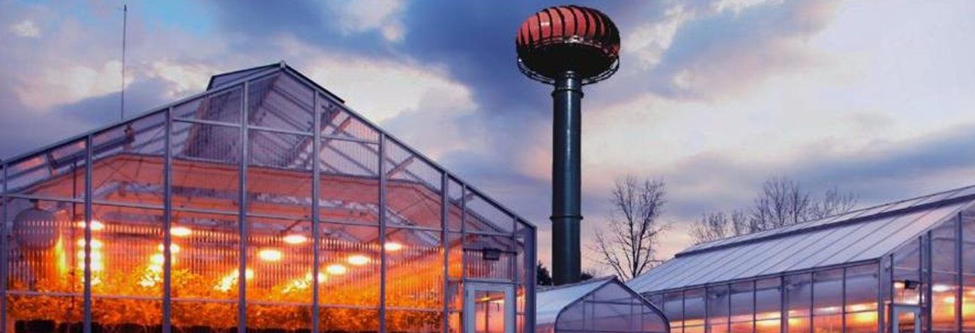
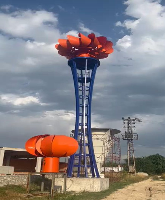
Vertical axis wind turbine with spherical rotor next to greenhouses
Technology 1

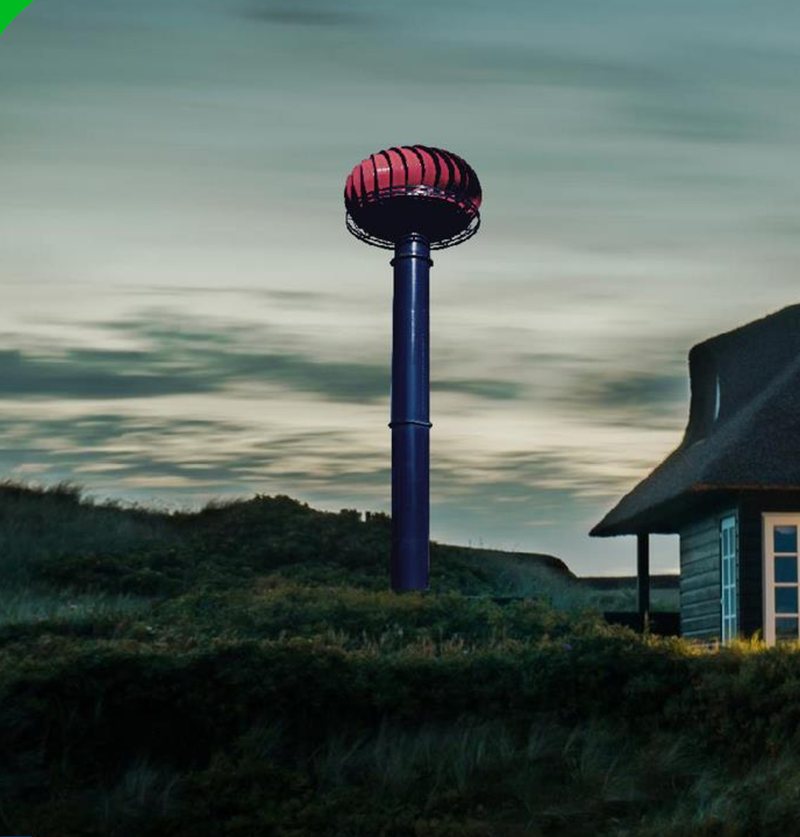
Vertical Axis Wind Turbine with Spherical Rotor

The sphere-shaped rotor receives wind from all directions – no yaw mechanism is needed. The system runs quietly, needs no fuel and adjusts itself in strong winds without having to be shut down.

  • Starts generating at 3 m/s wind speed
  • Receives wind from all directions, no yaw mechanism
  • Low-noise operation
  • Capacity from 1 kW to 1,000 kW
  • Self-adjusting in strong winds, no shutdown required
Where it can be installed
  • Roofs of large buildings and skyscrapers
  • Moving objects such as ships
  • Artificial air flows: cooling towers, industrial and ventilation fans, airfields

Two prototypes with 5 kW and 3 kW capacity have already been built in Bolu, Turkey.

Prototype of the spherical rotor wind turbine Spherical rotor wind turbine at dusk
Compact Systems
Capacity Rotor diameter Total height
5 kW 3.1 m 11.8 m
10 kW 4.4 m 15.3 m
30 kW 7.8 m 27.9 m
50 kW 9.1 m 31.2 m
Large Systems
Capacity Number of wings Rotor diameter Rotor height Tower height
50 kW 29 6.9 m 3.5 m 31 m
100 kW 43 9.1 m 4.8 m 44 m
200 kW 45 13.3 m 6.9 m 59 m
500 kW 45 25.5 m 12.2 m 76 m
1,000 kW 47 39.2 m 19.1 m 98 m
Technology 2

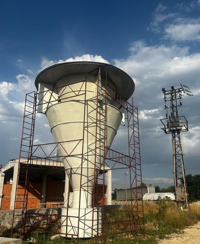
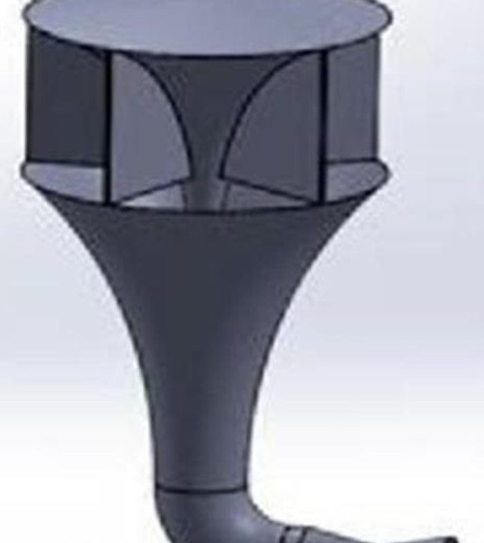
Venturi Wind Turbine

Venturi wind turbine under construction
Design model of the venturi wind turbine

The funnel-shaped venturi design accelerates the incoming wind, generating electricity even in very light winds. At the same time, installation costs are much lower than for conventional wind turbines.

  • Operates at wind speeds as low as 1 m/s
  • Much lower installation costs
  • Capacity from 5 kW to 1 MW
  • No fuel needed
  • Can also produce pure water from air humidity
Capacity Rotor diameter Height
5 kW 3.5 m 6 m
200 kW 23 m 34 m
500 kW 35 m 52 m
1,000 kW 50 m 70 m

Want to know which wind turbine suits your site? We are happy to advise you.

Request a consultation

Our Goals

Landscape

HIGH EFFICIENCIES

Our goal is to store and harness large quantities of liquid nitrogen, converting it into energy with higher efficiency than most other solutions.

HIGH CAPACITY

Our hybrid storage units are capable of storing immense amounts of energy, as the units are specially designed to release the power of the air.

COST EFFICIENCY

We work to be one of the most cost-effective solutions on the market, offering both high efficiencies and low installation costs.

Our Management Team

Martin Schausberger

Martin Schausberger

CEO - Managing Partner
Entrepreneur & Networker

Jakob

Jakob

Head of Engineering and Sales

Gerald

Gerald

Head of Electrical Engineering and Monitoring

Contact

Company Details

Firmenbuch nummer

FN 561599 g

EORI-Nummer

ATEOS1000117330

UID-Nummer

ATU77124639

Locations

Zell am Pettenfirst

Bruck 10, 4842 Zell am Pettenfirst - Austria

Ampflwang

Dr. Karl Renner Str. 13, 4843 Ampflwang - Austria